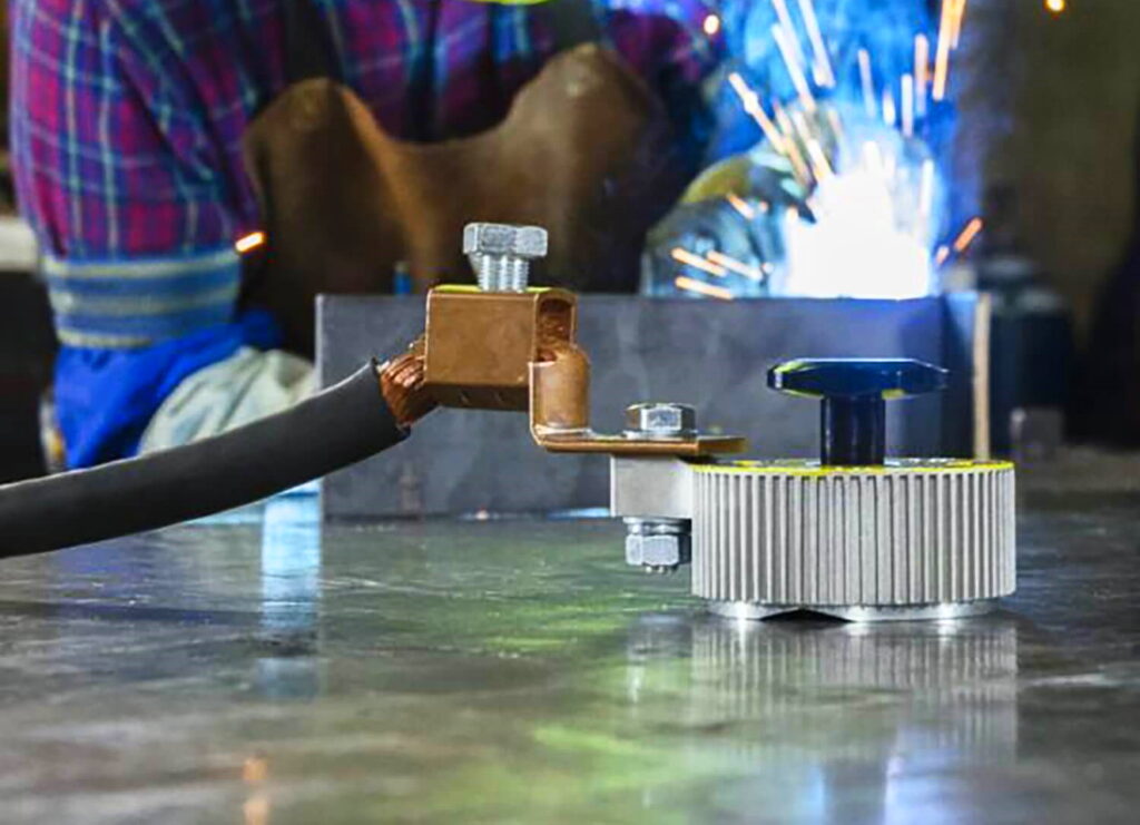

Engineers and welders use weld symbols during construction. During metal joining processes, weld symbols are meant to indicate different parts of the process. These symbols are usually found in fabrication and engineering drawings.
A weld symbol would differentiate between two sides of a joint using arrows and the spaces on top and under the reference line. You would create the weld based on the instructions under the reference line.
If you need help with weld symbols and welders, we have an extensive guide on the structure and the different types below. You can also get a pocket reference guide of these symbols if you’re finding it hard to remember each one.
The first thing to look at with
weld symbols
Trusted Source
Symbols and conventions used in welding documentation - Wikipedia
en.wikipedia.org
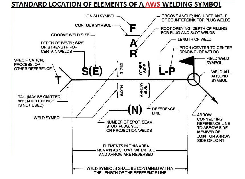
is the structure. The structure includes an arrow line, reference line, dashed line, and the basic symbols. If you understand what the structure means, you can easily read the fabrication or engineering drawings and use your welder for aluminum to create it. The structure must be arranged appropriately and understood for a welder to read it and know where the welds would be placed and how to put it together.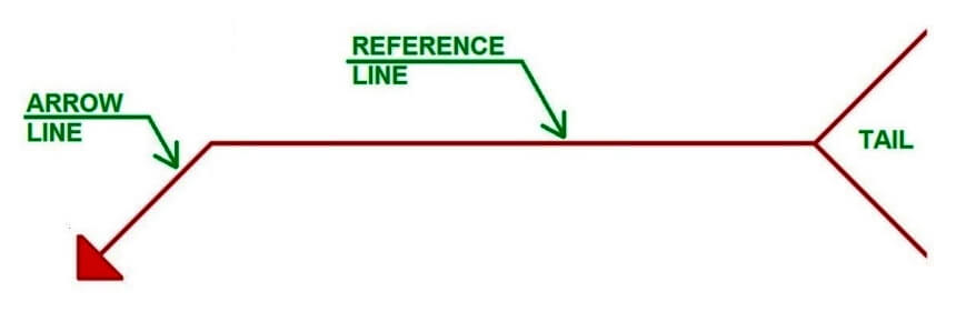
The arrow line is what connects the reference line to the joint where you would create the weld. The arrow line points towards a part of the diagram called the arrow side. The line can point up or down at any angle except for 180 degrees. It also has an arrowhead on top of it, which must touch the surface of the component you want to join and the weld location. The arrow will also point towards the component that would be prepared with single prepared components.
Another part of the structure is the reference line, which is the horizontal line. It can be seen as an anchor that ties all the welding symbols together. The horizontal line is connected to the arrow. Below the reference line, you have the arrow side, while above the reference line; you have the opposite side.
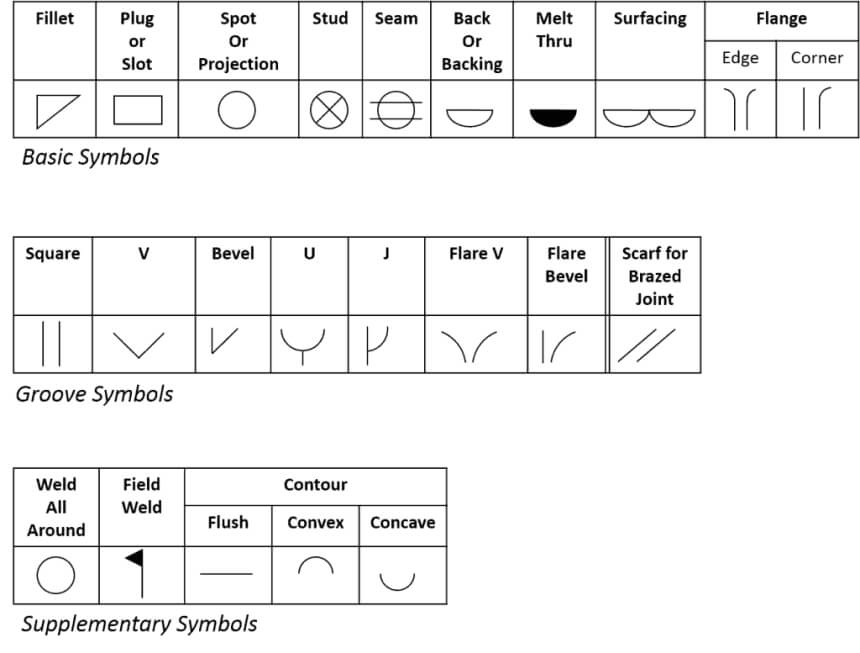 Apart from all the lines in the structure, you would also see different weld symbols. Different types of basic weld symbols make up the fabrication or engineering drawings. You can see different fillet, plug, spot, and many other kinds of weld types.
The dashed line is drawn either below or above the solid line of the weld symbol structure, but in most cases, it is under the solid reference line.
There are different kinds of weld symbols. The diagrams sometimes also feature corresponding symbols. You see a basic weld symbol on each welding position, usually placed close to the reference line. The position of the symbol depends on where the joint would be.
Weld symbols are small drawings that you can interpret in different ways. The symbols can also be shown on the arrow side or the other side. It’s one thing to know how to interpret the structure, but you also have to know the different weld types and interpret them. You also need to know what they mean to realize which welders you should use, from TIG welders to aluminum welders.
Here are the different weld types and the symbols that are used to depict them below.
Fillet weld is used to make corner joints, lap joints, and T joints. The fillet weld symbols are usually triangular in the cross-section, and its shape is usually not an isosceles or right triangle, but it is a triangle either way.
Most of the common weld types in the industry are used when the joint has two members joining together to create an intersection of 90 degrees. Although you can apply it at different angles, it would be more prominent at 90 degrees.
You can use a fillet weld symbol above or below the reference line or on both sides. When it is on both sides, it is called a double fillet weld symbol.
Another weld type is the plug weld, a round weld placed inside an existing hole. It is usually used when you weld one piece of metal to another piece. As for the plug, the weld symbol is indicated as a rectangle with a diameter symbol usually set beside the symbol on the left. You will also see the number related to the diameter.
Some engineering drawings don’t show the hole when they are printed, and so you have to be familiar with dimensions when figuring out where the plug weld is implemented. You can figure out the location of the plug weld by the centerline.
The spot weld is a simple kind of weld that is applied to the surface of one member. The member has adequate heat input to melt into the material used to create the faying surface. You can do this with no preparation beforehand.
The spot weld symbol is indicated by a circle, so it’s pretty easy to understand. It can be placed below, above, or right on the reference line. If you have the spot weld symbol on the reference line, it means that there is no side significance, which means that you can apply it with a resistance spot welder used in sheet metal work.
This is one of the types of single-sided butt welds, and the symbol is indicated by a horizontal line and a short vertical line. On top of the line, you also see a U shape. Whenever you see this symbol, you can identify it as a Single-U Butt weld.
When you see the single-U butt weld, you have both the plates with the corners cut. The plates usually run three-quarters down the plate, and it creates a pathway shaped like a U shape.
Another single-sided butt weld that you can use is the single-J butt weld. The symbol looks like a horizontal line and a long vertical line right in the middle. Then, there is a curve from the middle of the vertical line going up. The curve looks like a J.
The actual single-J butt weld has one of the plates as an arc through a partway, and the first end is a square. When you combine the two shapes, you have a unique shape.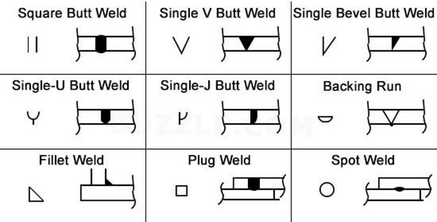
The single-V butt weld is another type of single-sided butt weld. The symbol is very simple to draw because it only looks like a horizontal line and a V shape right in the middle of the line. The V shape points upwards. Anyone can draw the symbol when putting together an engineering drawing.
When you see the single-V butt weld joint, you have a 45-degree weld prepared on both sides of the plate. It would also be a full depth on the plate. When you put the plates together, you get a V shape as it looks with the symbol.
The square butt weld is a joint without a weld preparation. It has both ends, which are square, and the symbol is represented by the two square angles on the symbol. The symbol looks like a horizontal line and there are two vertical lines on the main horizontal line.
You would put the two lines on the main horizontal line.
Another weld symbol type is the single bevel butt weld, which looks very similar to a single V butt weld. The symbol would look like a horizontal line, and then a vertical line right in the middle on the horizontal line. Then, you would see the diagonal line right at the middle, connected to the horizontal and vertical lines. So it looks like a slanting V.
When you see a single bevel butt weld, you have a 45-degree angle cut on one side going full depth. The other side retains a square shape.
A backing run symbol is also called a backing symbol, which is used when you use a backing bar to achieve complete joint penetration. The symbol is placed on top of the reference line from the basic weld symbol.
The backing bar symbol has the same shape as a plug weld or a slot weld symbol. Because of this, you have to clarify that you mean the backing symbol and make the context clear.
A backing bar is usually used as a supplementary symbol, but it can also be seen as one of the main weld symbols.
Supplementary weld symbols are symbols that are added to the main weld symbol for more explanation, instruction, or knowledge. Sometimes you need the supplementary symbol to be added to the main weld symbol so that it can be properly understood. There are different types of supplementary symbols.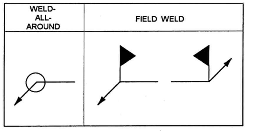
The weld all-around symbol looks like a simple circle, but it is usually placed at the point where you have the arrow and the reference line. This shows that the weld should be completed around the whole joint. You would usually see this symbol on a square or round tube and a plate.
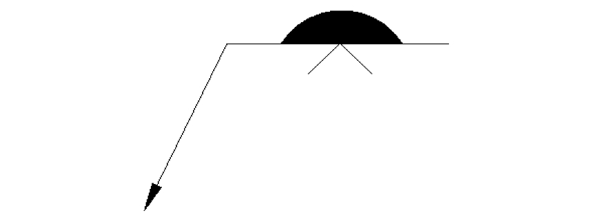
The melt-through is related to a groove wield, showing that you are getting a complete penetration with root reinforcement. You will see this symbol when the sheet metal is being welded, and there is a melt-through in the joints and seams. The melt-through includes a finishing contour.
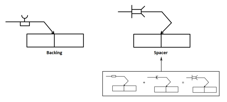
This is another supplementary weld symbol. It is used o
n a double groove weld. Here, you have the top and bottom prepared, and the spacer would be in the middle of the groove. You can identify the spacer by the rectangle that separates the reference line.
You can identify the field weld by the flag symbol, which is at the point where the arrow and reference lines meet. When you see a field weld, it signifies that that part would be assembled in the shop setting. The point of the flag must point towards the direction of the end of the reference line.
The consumable insert symbol is used when you have a welded joint as part of the weld. They come in different shapes, materials, and sizes. You will usually see the symbol standing opposite of the groove weld symbol.
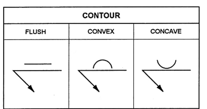
The contour finishing of a weld is indicated by the weld contour symbol. You can have a flat, concave or convex shape, and it is the final addition to the weld once it goes into service.
There are a variety of standards that weld symbols can meet, including the British, International, European, and American standards. Although these standards are sometimes similar, you should know the standard that you should use and how they are different.
This standard belongs to the American Welding Society Trusted Source American Welding Society The American Welding Society (AWS) was founded in 1919, as a nonprofit organization with a global mission to advance the science, technology and application of welding and allied joining and cutting processes, including brazing, soldering and thermal spraying. AWS strives to move the industry forward in both thought and action, as well as inspire new generations to see the exciting career opportunities available today. www.aws.org , which shows the method that shows particular brazing, welding, and more. When you see the AWS A2.4, you see the examples for the design and interpretation of symbols, including the fillet welds, slot welds, seam welds, stud welds, groove welds, plug welds, spot welds, edge welds, and surfacing welds.
There are other standards that you can use apart from the one provided by the American Welding Society.
There is the British Standard for weld symbols, which is BS EN 22553. The standard includes the identification of the welding process for engineers and welders in Britain and other related places.
There is also the International Standard for weld symbols, which is called ISO 2553 standard. You can also use the European Standard.
Weld symbols might look confusing at first glance, and there’s no doubt that there’s a lot that you have to learn. From the entire structure and the main symbols to even the supplementary symbols, you will have to memorize all symbols and their meanings if you want to interpret any engineering or fabrication drawing. If you’re having trouble with that, you can use a welder symbols quick card instead.
One of the reasons why weld symbols are important is that they make sure you have consistency and high quality whenever you construct or engineer. It would make it easy for welders to figure out where to put their welds, how large they should be, and what kind of weld they should use.
Once you get the hang of these weld symbols, you would be able to discover what they mean by just glancing at them on a drawing.